
hardware i
building a ddr pad

a few months ago i wrote “i think i want to build my own ddr machine in spring 2025”. it is still spring and i now have a working pad that other people have played on!
this post is divided into 3 sections:
1. high-level process reflections (potentially interesting for most people)
2. fun things i learned while building a pad (interesting if you enjoy hearing about hardware details)
3. streamlined instructions for building a pad (not relevant for most people)
thanks to adil, brian, kelsey, shihao, sonnet 3.7 for helpful discussions throughout the process
1. process reflections
hardware sucks. i never have the materials i need at home and oftentimes they’re heavy so transporting them from place to place requires ubers and tires me out. part of me wants to retreat into my computer and only touch software for the rest of my life. another part of me is masochistic and finds the logistical problems really fun to work through (i think this is the same part of me that likes planning travel). also ai is about to solve knowledge work so everyone should be doing hardware
there are a lot of ddr guides on the internet. i looked through a few of them and found them unsatisfying either because a) they explained how to build a static pad (ie. no responsive / tactile feedback) b) they used tools or designs that felt unnecessarily complicated. i wanted to try deriving everything from first principles and getting the simplest possible build so i ended up ignoring everything and brainstorming with friends + claude
by far the most demoralizing and time-consuming step was acquiring parts. i spent a month (mid-april to mid-may) planning and ordering materials; the process looked something like scope out part of the design, order relevant parts and wait 3 days for them to arrive, play around with the parts and realize they’re not quite what i need, order more parts, repeat. (i tried to derisk purchases before making them but as someone with no hardware experience it was difficult to predict how various parts would fit together or what it would feel like to step on things.) i think it’s interesting that most of the difficulty was in this initial stage; once i had all the right parts it only took a week to build a functional prototype
the first prototype sort of worked but was terribly unreliable because i’d been careless during assembly (eg. lots of loose pieces moving around all the time). that was intentional as the goal was just to iterate quickly and validate high-level design; once that was done i demolished the prototype and started over, which felt a bit sad but i’m learning to kill my darlings. it reminded me of one of my favorite calvin and hobbes panels:

(the older you get the more you realize the dad is kind of right - when building structures with novel materials or designs we often do just load test them until they break and then rebuild them. of course there is some simulation / theory too but it only gets you so far)
anyway, after starting over it took two days to build a second pad that was quite reliable. the process accelerates exponentially as you clarify exactly what you need. i spent almost the entire spring thinking that there was no way i’d finish in time and then it came together all at once
at some point in may i became very disoriented. i was spending my free time thinking about various tools and mechanisms, and then i realized that i don’t understand anything in my life! there was one morning in particular where i walked into my office building and noticed i had no idea how any of it was constructed, and then i panicked a bit. some of my mech-e friends tell me they have seen so many mechanisms that the world feels deeply intuitive and one day i would like to get there. idea for a new app: google lens except it explains the physical structure of everything around you
2. fun things i learned while building a pad
2.1 cutting aluminum
at some point i ordered 1mm aluminum sheets and needed to cut them into flat metal bars (i.e. rectangles). i thought this would be simple because aluminum is soft and 1mm is thin, but it turned out to be very difficult
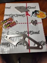
most people recommended tin snips or bolt cutters, which are basically more powerful scissors, but these all operate via shearing (push material on one side of the cut upwards and material on the other side downwards) so you end up deforming the metal significantly. typical laser cutters also don’t work as aluminum is too reflective and has high thermal conductivity so the heat dissipates quickly. if you have a saw with the right blade that can work. unfortunately i didn’t, so i eventually gave up and used sendcutsend, which lets you specify how you want your sheet metal cut and then ships it to you. they’re also faster + cheaper than amazon and give you candy as part of the shipment
2.2 tapes
there are so many kinds of tape! i ended up relying on 3 tapes i hadn’t touched before, which i’ll explain below
2.2.1 copper foil with conductive adhesive
sometimes you want your tape to be conductive (eg. to connect wires to metal without soldering, or to shield circuits from interference without using a cage), so the common options are copper foil and aluminum foil tape. however, most foil tapes aren’t actually made for this use case - i visited several hardware stores and they had metal foil tapes in the plumbing / hvac section (eg. to tape over holes in hvac ducts), but most of these applications only require heat insulation rather than conductivity, so they use nonconductive adhesive. conductive adhesive tape seems a lot less common (was not at discount builders, ace hardware, etc) and more expensive (you get conductive adhesive by mixing regular adhesive with metal particles) so i gave up and ordered online
2.2.2 polyethylene foam tape
this is basically tape backed on 1-2mm of plastic foam; you can get the same effect with more work via regular double-sided tape + foam. it’s very springy and compresses / expands back to its usual depth easily, so i use it to tape together parts that should move back and forth under pressure. unfortunately it has a bad initial smell because of off-gassing
2.2.3 vhb tape
this is the strongest tape! so strong that i was unable to get the tape out of its packaging without a knife and there are youtube videos with 70k+ views explaining how to peel the cover off the tape. this means it is slow to work with (annoyingly sticky, hard to cut, etc) but very durable, often good enough to replace screws
very few people actually know how tape works? you have a viscous (half-)liquid adhesive that flows into cracks / imperfections in the target surface when you apply pressure, and then van der waals forces create adhesion once the surfaces are tightly coupled. i don’t fully understand why vhb tape is so strong but it seems like the key is using an adhesive made out of acrylic polymer, so that a) the polymer chains can contort and easily match the shape of any target surface b) there is a high density of dipoles so you get more van der waals interactions
2.3 mechanisms
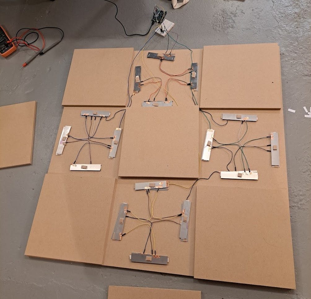
i decided early on that i wanted my sensors to accomplish two functions at once: a) register footsteps to the ddr software b) provide tactile feedback to the player. in hindsight this was probably not smart, since it requires the sensor parts to accommodate physical motion (which causes distortion) while remaining intact enough to be a reliable sensor. you could imagine an alternate design where these functions are separated, eg. the sensor is some piezoelectric component that does not need to move, while the tactile feedback comes from springs. this would probably be simpler to maintain long-term, with slightly higher upfront cost
here’s a simplified version of the sensor design i used - essentially when pressure is applied the top bar should bend and make contact with the bottom bar
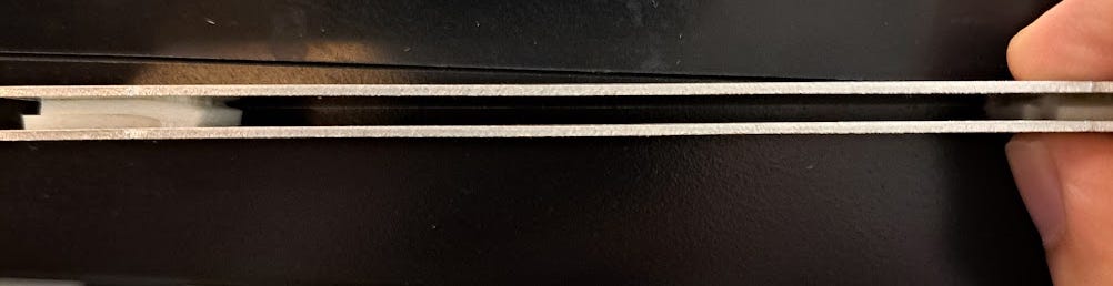
it made sense in theory but wasn’t easy to reason about in practice because the mechanism revolves entirely around deformation, which i’d never given much thought to. i think this is related to a major problem with how physics is taught in schools - most people will only ever go through mechanics classes that eg. assume all bodies are rigid and will never be asked to think about whether or not any given scenario satisfies those assumptions, so it’s easy to accidentally apply a model of physics to scenarios it’s not meant for. for instance: when i tested each sensor in isolation they worked fine, but as soon as i put my sensors under a piece of wood they stopped working because changes in pressure distribution resulted in different kinds of deformation; electrical connections kept failing because wires were being connected to a piece that kept bending up and down; and so on. (the solution i settled on: put more foam on top of the sensor to control the distribution of pressure, and then tape wires to areas that receive no pressure)
3. streamlined instructions for building a pad
for ddr software you can use stepmania / outfox, with an arduino to communicate between the pad and the computer. the microcontroller code is pretty minimal (listen on any 4 pins and send up/down/left/right keystrokes when the corresponding pin is active). i’m just going to explain how to create a single ddr tile as assembling the full board is straightforward once you know how to make individual tiles
you need: a 1’ x 1’ block of mdf wood, 8 1’’x5’’x1mm aluminum bars, polyethylene foam tape, vhb tape, copper tape, lots of wires, some base you’re building the tile on top of (in my case a 3’ x 3’ piece of wood). the amortized cost is around $15, dominated by the cost of getting 1mm aluminum
i. mark out the 1’ x 1’ region of the base you want the tile to sit on top of
ii. put some foam tape on the ends of each aluminum bar
iii. place four of the aluminum bars near the edges of the region, foam facing up. apply vhb tape underneath the bars to stick them to the base
iv. connect the four bars to ground / each other with wires and copper tape
v. stick the other four aluminum bars on top of the first four bars, foam facing down. the foam on the top bar should connect with the foam on the bottom bar
vi. add additional foam to the top of each sensor
vii. connect the four top bars to each other / some pin on the arduino with wires and copper tape. each sensor should have this overall structure:
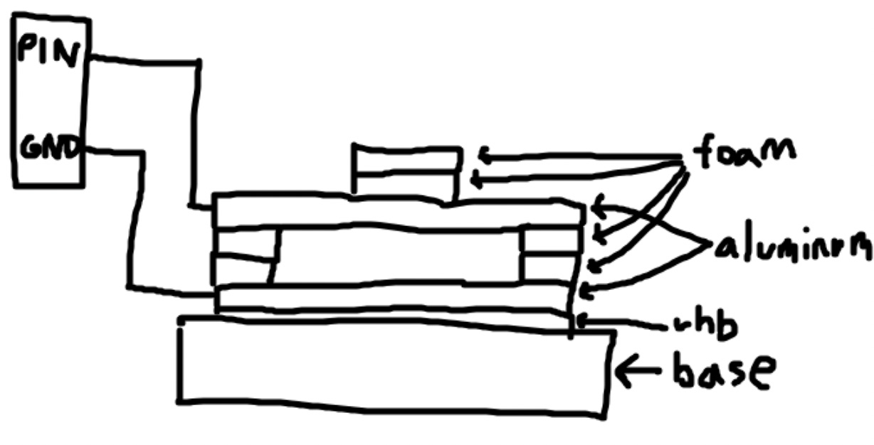
viii. place the 1’ x 1’ wood tile on top of everything else. you’ll notice it’s just resting on top of the sensors and not actually stuck to anything underneath it. in principle we could stick it to the sensors with vhb but i decided i’d rather keep the tile easily removable for debugging. this means it has the potential to slide around horizontally and tilt vertically (using the sensors as pivots) as you apply pressure. in practice you can restrict the motion with physical obstacles (eg. i added extra foam underneath the tiles but probably a lot of approaches work)
1 outfox is good but i used to have this problem where i could increase but not decrease the global offset with hotkeys and to decrease i had to edit some file
2 key for sensors is to be overly insensitive and then penny mod the shit out of it :)
3 this is super awesome vnice!
FIRE